5 Multi-phase flow

5.1 General
Control valve sizing theory for multiphase flow is not nearly as well developed as it is for single-phase fluids. Sizing control valves for a pure liquid or gas flow can be done using existing standard sizing equations based on flow dynamics and valve-specific sizing coefficients. When a control valve is sized for a two-phase flow, which is usually a mixture of liquid and gaseous fluid, no generally accepted standard method exists. This is because, in two-phase flow, liquid and gas cannot be mathematically described in a simple and exact way at the same time. Also, experimental research requires a lot of tests with different kinds of mixtures and mass fractions using various valve types. For this reason, it is not possible to size valves for multi-phase flow with the same accuracy as for single component streams.
A large part of this section concentrates on sizing control valves for a particular multi-phase fluid, i.e. pulpstock. Valmet's flow control business line has done a lot of the basic research on determining the behavior of pulpstock flow through control valves. As a result of this research, this manual now introduces a method for sizing control valves for pulpstock flows. This method can be applied to all rotary control valve types.
5.2 Two-phase flow of liquid and gas
The method presented here is based on a homogeneous flow theory which assumes that liquid and gas move with the same velocity and are homogeneously intermixed. The method can be applied in the following two cases of two-phase flow:
Case 1: Single-component, two-phase flow (e.g. steam and liquid water)
Case 2: Two-component, two-phase flow (e.g. crude oil and natural gas).
Sizing equations
Homogeneous flow theory is based on average properties such as the density and velocity of a two-phase mixture. After necessary average properties have been determined, a valve can be sized with equations similar to the standard equations for single-phase flow.
The density of a two-phase flow is calculated using separate densities for both phases on the upstream side of a valve. In addition, gas expansion must be taken into account when gas flows through the valve. The density of the mixture, something that we call effective density, can then be formulated as in equation (77).


Choked flow
There are not enough experimental studies of choked two-phase flow to allow exact terminal pressure drops to be determined. In control valve sizing, the terminal pressure drop approximation is thus performed using a combination of the terminal pressure drop values of pure gas and pure liquid. Pure gas flow chokes when the pressure drop reaches the value given by equation (79).

In a case where all the fluid is in the liquid-phase flow, choking will start when the pressure drop in equation (80) is reached. When a small fraction of gas is added to the flow, the choked flow pressure differential changes, but it is still quite close to the value in equation (80). An increased mass fraction of gas will further change the terminal pressure drop that produces choking, but it is not clear how this happens in control valves. Finally, when all the fluid is in the gas phase, choking will start with a pressure drop as in equation (79). Theoretical calculations and flow tests have been performed to determine the terminal pressure drop for ideal nozzles. These results show that the linear relationship between the terminal pressure drop in the liquid and gas phase as a function of gas mass fraction is accurate enough to describe the terminal pressure drop in choked two-phase flow. Therefore, it can be formulated as in equation (81).

When the actual pressure drop exceeds the value of equation (81), the two-phase flow is considered to be a choked flow, and the pressure drop in equation (81) is used for the valve sizing equation (78), and, to calculate the expansion factor Y. Note that the minimum value for expansion factor Y is Ymin(= 0.667).
Accuracy
Due to the nature of the two-phase flow of liquid and gas, it is impossible to adequately describe the various possible forms of flow using a single mathematical formula. The method presented here is based on what we call homogeneous flow theory, an approach which assumes that the velocities of liquid and gas are the same and that they are completely intermixed. This is a fairly common flow type, so the method described can be utilized in many two-phase flow applications.
The accuracy of sizing decreases if the form of the flow deviates from the type described. The following forms of flow are possible in a pipe:

Phase changes in the liquid and gas, vaporization of the liquid, or condensation of the gas into liquid make it difficult to calculate mass fractions and effective density. These factors in sizing accuracy are especially evident with single-component two-phase flow. When the pressure decreases and the temperature is almost constant, the liquid tends to evaporate whereby the mass fraction of vapor and the required valve capacity increase. On the other hand, something called the metastability phenomenon tends to 'slow down' the phase change. In this phenomenon, the liquid does not vaporize at once in the vena contracta although the thermodynamic equilibrium of the substance would indicate this. Instead, vaporization occurs only after the vena contracta.
The effect of mass fractions on sizing accuracy is especially visible with small mass fractions of vapor. For example, a change in the mass fraction of a saturated 7 barA water and steam mixture from 1% to 2% causes a 73% change in the specific volume of the mixture. This means that the required capacity increases by about 30%. On the other hand, if the mass fraction of the flow changes from 98% to 99%, the specific volume of the mixture changes by 1%. If the mass fractions with single-component two-phase flow are not exactly known, the sizing can be checked by assuming the whole mass flow as vapor flow. This guarantees that the valve capacity is adequate in all situations.
Noise
There are no methods for predicting noise in two-phase flow. In practice, estimation of noise in two-phase flow is very difficult. It is known from experience that cavitation noise in pure liquid flow is lower if, for instance, air is mixed with the liquid. Air bubbles attenuate the pressure waves created by the collapse of cavitation bubbles.
5.3 Pulpstock
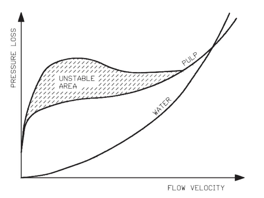
Paper and pulp mills use a large number of control valves for throttling the flow of pulpstock. As the selection process determines the pumping energy 'burnt' in the control valve and the piping, the costs of both building and running the process are largely determined by how the throttling control valves are sized and selected. Correct selection of the pulpstock control valves can determine the the optimal size selection of pumps and piping. In the past, over-dimensioning of pumps and valves has been used for all the uncertainties in the behavior of the pulpstock flow. Rough correction coefficients have been used to account for the greater capacity (Cv) requirement of pulpstock compared with water. However, new studies go a long way towards predicting how pulpstock exactly behaves in control valves. Furthermore, they significantly help improve the accuracy of sizing calculations. Previous studies, mainly performed to evaluate consistency effects on pipe flow, indicate that pulpstock flow behavior is highly dependent on flow velocity, as shown in figure 70.
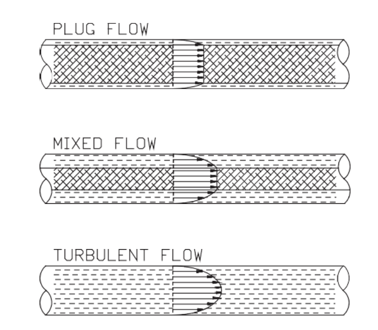
When the flow velocity of the pulpstock is very small, it flows in the pipe like a solid plug and forms 'rolls' which spin between the plug and pipe wall. As the flow velocity is increased, the flow changes into a plug flow, in which the fibers no longer touch the pipe wall as there is a narrow boundary layer between the plug and the pipe wall. In this area, the pressure loss remains relatively constant in spite of flow velocity changes, and it can even have an inverse relation to the flow velocity increase (unstable area in figure 71). As the flow velocity is further increased, the thickness of the boundary layer increases, and turbulence starts to appear in the boundary layer and on the surfaces of the pulp plug. The centre of the pulp plug remains plug-like. This is called mixed flow. When the flow velocity is further increased, the pulp plug disappears and the whole flow cross-section becomes turbulent.

Figure 71. The piping pressure loss in relation to flow velocity for pulpstock and water describes the changes in piping pressure loss at different flow velocities in pulpstock and water flows.
The three basic forms of pulpstock flow are illustrated in figure 72.

Figure 72. Pulpstock flow types.
Note also that at high flow velocities, as in figure 71, the pressure loss of the pulpstock can be lower than that of water.
5.3.1 Studies about pulpstock
Valmet's flow control professionals have performed over 2000 measurements of pulpstock flow through control valves. These tests were performed on three different types of quarterturn control valves in three different sizes (50 mm/2", 100 mm/4" and 200 mm/8"). The pulp stocks used were bleached kraft (sulphate pulp), thermo-mechanical pulp, and recycled pulp. The tests resulted in an empirical correction coefficient (k), which is presented in appendix J. The coefficient (k) is determined by equation (82).

Note that a correction of the flow rate is used instead of a correction in the required Cv value. This is done to size the valves with the correct sizing parameters pressure recovery factor (FL) and cavitation index (z), both of which relate to the real opening of the control valve.
The differences in the results for different size control valves and different quarterturn valve types were found to be insignificant, which justifies using a single set of correction curves for each type of pulpstock. The correction coefficients (k) are given in appendix J for both SI and US units.
5.3.2 Pulpstock behavior in control valves
The following relationships have been established in the pulpstock flow through control valves:
-
The coefficient (k) increases with the increase in differential pressure.
-
The coefficient (k) decreases with the increase of pulp consistency.
When the consistency is lower than 2%, there is very little difference between water and pulp flow rates, and sizing can be done without a correction coefficient (k), using water sizing equations only.
The effect of differential pressure on pulp flow
The differential pressure across a pulpstock control valve has the largest effect on the correction coefficient k. In particular, very small differential pressures require a large correction (= small k value).
The effect of consistency on pulp flow
Tests clearly indicate the effect of pulp consistency on the correction coefficient. When the consistency is between 1.5% and 2%, the pulpstock behaves much like water. When consistency increases to, say, 12%, the value of the correction coefficient k can, depending on the type of pulp, be in the range of 0.3 0.6 at small differential pressures. This finding is very important for selecting valves for MC pump discharge control. In order to allow for small k coefficients, expanded outlet valves provide a higher capacity (Cv) than standard segment valves.
The effect of valve diameter and style on pulp flow
Valve diameter has a very small effect on the correction coefficient, i.e., the larger the valve, the lower the k coefficient. This difference is so small that for practical purposes, correction coefficients used for sizing purposes can be kept constant for all valve sizes. No measurable differences have been found between the ball, segment and butterfly valve k coefficients. Therefore, the coefficients for all rotary valve styles are the same.
The effect of other factors on pulp flow
The tests performed to develop the coefficient k curves were done using valve inlet pressures common to typical pulp and paper mill pump heads. They can be considered constant for typical pulp and paper mill environments, independent of inlet pressure. Various freeness factor samples from each pulp stock brand were used for testing. No significant effect was observed due to freeness variation.
In light of these experiments, k coefficients can be expressed as a function of pressure drop, pulp consistency and pulpstock type with sufficient accuracy for control valve sizing calculations.
5.3.3 Control valve sizing for pulpstock applications
Control valve sizing for pulpstock applications is performed using an 'equivalent water flow rate' and water sizing equations. The 'equivalent water flow rate' is derived from equation (83).
After calculating an equivalent water flow rate, the sizing is done utilizing standard IEC/ISA sizing equations for water, as presented in chapter 3.
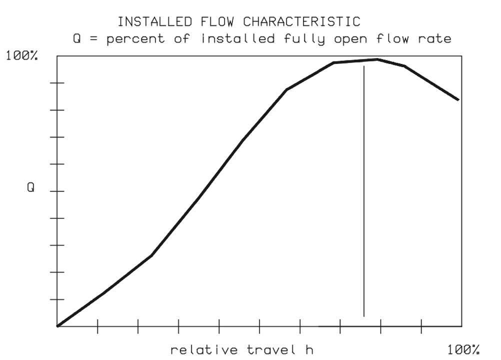
Figure 73 shows an example of an installed flow characteristic for a 10% mechanical pulp control valve in a typical process piping system.

Figure 73. Installed flow characteristic for a 10% pulpstock control valve.
Figure 72 shows that when the valve opening is already relatively large, the actual flow decreases if the valve is further opened. This kind of situation has to be avoided in order to maintain the fluid flow control of the process.
In the described case, we advise to set the valve maximum opening at about 55% to guarantee process controllability, and to use a valve with an expanded outlet. When the valve maximum opening is set at 55%, increasing the valve opening, the capacity (Cv) increase produces a constantly larger flow.
5.4 Slurries
A typical two-phase flow of a liquid and solids is wet slurry, a mixture of a liquid and solid particles. Suspensions are slurries if the particle sizes are so small that the mixture remains unseparated for a long time. Suspensions can be treated as non-Newtonian fluids, where basic liquid equations can be applied to the calculated 'apparent viscosity' for the suspension.
Settling slurries are suspensions in which particle size is bigger than 0.25 mm (0.01 in). These can be calculated as liquids, as long as the two phases can be assumed to flow through the control valve as a homogenous mixture, with the densities of different phases close to each other, and viscosity small enough to guarantee effective mixing. In that case, the density (ρ) is taken as the effective density (ρE) weighted mass ratios of liquid and solids.
Solving the two-phase flow of suspensions is complicated because it is a complex flow type. It involves calculating the 'apparent viscosity' and determining the necessary parameters as well as a liquid calculation taking into account the Reynolds number. The details of the calculation are not presented here but are available from valve manufacturers.
A typical two-phase flow of dry slurry is a mixture of gas and solids. This kind of mixture is rarely controlled by conventional valves due to mechanical problems like erosion and plugging. If a control valve is to be sized for dry slurry, equation (78) gives the best results, although it is slightly conservative. In this case, the density of the mixture is taken as the effective density in equation (77), where the liquid is replaced by a solid.